Leave Your Message

How to Understand Continuous Ball Mill Working Principle?

Understanding the Continuous Ball Mill Working Principle is essential for anyone studying modern mineral processing. Unlike a batch mill, a continuous ball mill receives feed while finished slurry leaves the discharge end. Inside the rotating shell, steel balls lift and drop through the ore. Impact and abrasion reduce particle size. Simple in appearance. Not simple in operation.

Industry data shows why this equipment deserves careful analysis. The Coalition for Eco-Efficient Comminution (CEEC) reports that crushing and grinding can consume a substantial share of mine-site electricity, often approaching 25% of total energy use. The International Energy Agency also identifies mineral processing as an important energy demand in the expanding clean-energy supply chain. These findings make mill efficiency more than a maintenance concern. It affects production cost, emissions, and resource use.

A practical explanation must connect theory with measurable plant conditions. Feed size, hardness, ball filling, mill speed, liner design, slurry density, and residence time all influence performance. Operators may hear the mill produce a deep rolling sound, while the motor load rises when the feed becomes harder. That sound is useful, but it is not a reliable control method alone. Instruments and laboratory tests remain necessary. The Metso comminution handbook and professional mineral-processing guidance both emphasize controlled operating variables and regular sampling. Yet no model predicts every ore body perfectly. Real feed changes. Small errors in water addition can alter classification and reduce capacity. This guide examines the working sequence, energy transfer, key components, and practical limitations behind continuous ball milling.

How to Understand Continuous Ball Mill Working Principle?

Mill Anatomy: Shell, Liners, Grate, Feed Chute, and Discharge Port

How to Understand Continuous Ball Mill Working Principle?

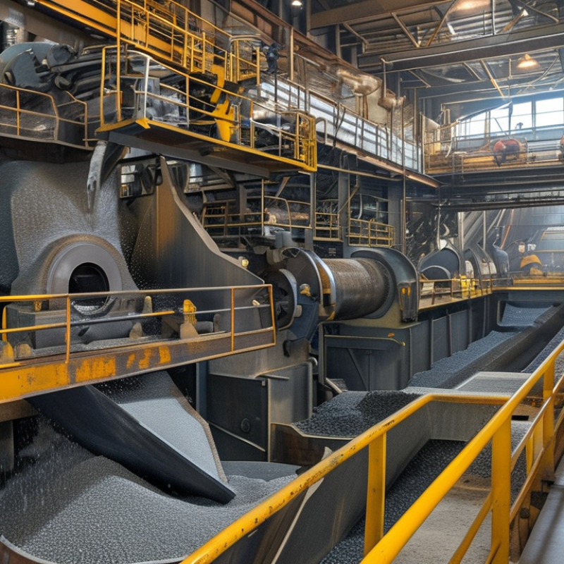
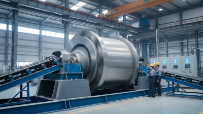
A continuous ball mill moves ore through a rotating shell without stopping the grinding cycle. The shell creates lifting action, while steel balls fall and break particles through impact and abrasion. The liners protect the shell and shape the internal motion. Lifter height, liner wear, and ball size influence power draw and product fineness. The Coalition for Eco Efficient Comminution reports that comminution may consume about 3% of global electricity and up to half of a mine’s energy. Small mechanical losses can become expensive.

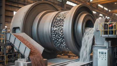
The feed chute must deliver material steadily, not in sudden surges. Uneven feeding changes the mill’s load and may reduce grinding efficiency. Inside the shell, slurry or dry material travels toward the grate. The grate controls how quickly particles leave the grinding zone. Its openings must suit the target product size. A blocked grate can raise pressure and disturb the discharge pattern. The discharge port then removes ground material for classification or further processing. It sounds simple, but field conditions are rarely simple.

Tips: Check liner profiles during scheduled inspections, and record wear trends instead of relying on visual guesses. Measure feed rate, motor power, bearing temperature, and discharge density together. CEEC energy studies support this broader approach because grinding performance depends on the whole circuit. I have seen operators adjust ball charge first, although a worn grate or unstable feed was the real problem. That mistake is worth reconsidering.

Feed Control: Maintain 25–40% Ball Charge and Steady Material Flow

How to Understand Continuous Ball Mill Working Principle?

Feed control strongly affects how a continuous ball mill performs. A practical starting point is a 25–40% ball charge by the mill’s internal volume. This range supports effective impact and abrasion without crowding the grinding space. Too few balls can leave coarse particles behind. Too many balls may reduce material movement and increase power demand.

Material flow must remain steady. Sudden surges can overload the first grinding zone and cause uneven residence time. A stable feeder delivers a consistent layer of material. Operators should check feed rate, moisture, particle size, and discharge condition together. Small changes matter. Wet feed may form cushions around the balls. Dry, fine feed can create dust and reduce useful contact.

During inspections, current readings, vibration, sound, and product fineness provide useful evidence. A sharp motor-current rise may indicate overfeeding or poor discharge. Unusual rattling can suggest an unsuitable ball distribution. These signs need confirmation, not guesswork. This rule is not universal. Different ores and mill dimensions may require adjustment. I have seen operators maintain the target charge but overlook unstable feeding, which still produced inconsistent grinding. Recording each adjustment helps reveal what actually works. Good control is a measured process, not a fixed setting.

Size Reduction: Cascading and Cataracting at 65–75% Critical Speed

How to Understand Continuous Ball Mill Working Principle?

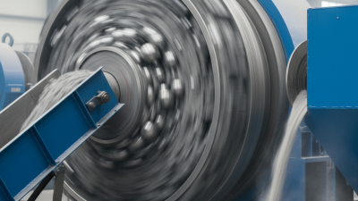
A continuous ball mill reduces ore through repeated impact and abrasion. At 65–75% of critical speed, the charge shows two movements: cascading and cataracting. Cascading occurs near the lower shoulder, where balls roll and slide across the particle bed. Cataracting begins higher on the mill wall, sending larger balls through the free space. That falling impact breaks coarse particles.

A 2023 review in Minerals Engineering notes that industrial tumbling mills commonly operate within this 65–75% speed range. Below this range, grinding becomes too gentle. Above it, centrifugal effects can hold balls against the shell. The result may be more noise, higher wear, and weaker size reduction. It sounds simple. It is not.

The International Energy Agency reports that cement production consumes roughly 7% of global energy, with grinding demanding a significant share. In mineral processing, energy reviews from the Coalition for Eco-Efficient Comminution commonly place comminution near 25–50% of a mine’s electricity use. Operators therefore adjust ball filling, feed rate, slurry density, and liner lift carefully. A practical mill may show cascading at one zone and cataracting at another. The charge is rarely perfectly uniform. That imperfection matters. Small changes in moisture or feed size can shift the impact point, alter product size, and increase recirculating load. Field observations still deserve attention, because laboratory behavior may not represent a full-scale continuous circuit.

Continuous Transport: Residence Time, Slurry Density, and Airflow Control

How to Understand Continuous Ball Mill Working Principle?

Continuous transport determines whether a ball mill operates smoothly or wastes energy. In practice, residence time depends on mill volume, feed rate, ball filling, and slurry viscosity. The SME Mineral Processing and Extractive Metallurgy Handbook reports that wet grinding commonly uses 60–80% solids by weight. Higher density can improve throughput, but excessive solids restricts transport and increases circulating load. A practical control room check compares feed flow with discharge density every 15–30 minutes. The number is useful, not perfect.

Residence time is often estimated from effective mill volume divided by volumetric feed rate. Many continuous circuits operate within several minutes to roughly half an hour, although ore hardness changes this range sharply. Wills’ Mineral Processing Technology notes that classification strongly affects product size and mill stability. A small change in cyclone pressure can therefore alter the mill’s apparent residence time. It happens quietly. Operators should watch discharge texture, motor load, and particle-size results together.

Airflow becomes critical in dry grinding and air-swept systems. Excessive airflow can carry coarse particles forward, while weak airflow allows heat and dust to accumulate. Industrial ventilation guidance commonly targets controlled negative pressure and stable conveying velocity, rather than maximum air volume. Temperature sensors near the outlet provide useful evidence. Still, one sensor can mislead. Moisture, liner wear, and false air leakage may distort the reading. Reviewing trends against daily production data is more reliable than reacting to one alarm. Industry energy studies, including the International Energy Agency’s mining analyses, consistently identify grinding as a major energy consumer, making transport control financially important.

How to Understand Continuous Ball Mill Working Principle? — Continuous Transport: Residence Time, Slurry Density, and Airflow Control
Operating Dimension Typical Value or Range How It Affects Continuous Transport Monitoring Method Practical Control Considerations
Material residence time Commonly about 10–60 minutes in continuous grinding circuits; the actual value depends on mill volume, filling, feed rate, and slurry rheology. Longer residence time generally increases grinding exposure and can improve fineness, but may reduce throughput and increase overgrinding risk. Estimate from effective mill hold-up and solids or slurry feed rate; confirm with tracer testing when accurate transport data are required. Residence time is not a fixed machine constant. Changes in feed rate, slurry density, grate or discharge conditions, and internal classification can alter the effective value.
Residence-time relationship τ ≈ Mhold-up / ṁfeed A higher internal hold-up increases residence time, while a higher mass flow rate decreases it if the mill load remains stable. Use mill load measurements, feed weighing, density data, and discharge flow measurements. The calculation is an engineering approximation. A continuous ball mill may show a residence-time distribution rather than one single residence time because of mixing, short-circuiting, and dead zones.
Slurry solids concentration by mass Often approximately 60–80% solids by mass for wet grinding, depending on ore characteristics, product size, and circuit design. Increasing solids concentration can raise throughput and reduce excess water, but excessive concentration increases viscosity and may restrict transport through the mill. Measure slurry density with an online density meter or calculate it from accurately measured mass and volumetric flow. Operate within the range established by test work. The optimum value depends on particle size, mineralogy, viscosity, and the required product fineness.
Slurry density Typically around 1.5–2.1 t/m³ for many mineral slurries; the value varies with solids concentration and particle density. Density influences pumping resistance, mill hold-up, power demand, and the transport speed of particles through the grinding zone. Use a calibrated density gauge, pressure-based measurement, or laboratory density checks for verification. Sudden density increases may indicate insufficient water addition, a blocked discharge path, or an excessive solids feed rate.
Water addition Adjusted to maintain the target slurry density and flowability; the required rate is process-specific rather than universal. Additional water lowers slurry density and viscosity, generally promoting transport, but excessive dilution can reduce grinding efficiency and increase downstream water load. Use a flowmeter together with online slurry-density and product-size measurements. Water control should respond to both solids feed changes and density feedback. Feed-forward control is useful when ore feed rate changes rapidly.
Mill filling level Ball charge is commonly operated within approximately 20–35% of the mill volume in many grinding applications; total material hold-up is higher. Higher filling can increase collision frequency and hold-up, but excessive filling may restrict movement, raise power demand, and reduce effective transport. Infer from power draw, mill weight or bearing pressure, sound measurements, and periodic inspection where available. The suitable filling level depends on mill diameter, speed, liner design, ball size, feed size, and discharge arrangement.
Mill rotational speed Many ball mills operate below critical speed, often approximately 65–80% of critical speed for tumbling-grinding service. Speed affects the trajectory of the grinding media and the balance between cascading and cataracting motion, which influences both breakage and transport. Monitor motor speed using the drive control system and compare it with the calculated critical speed. Operating too close to critical speed can cause excessive centrifugal motion and reduce useful impact. The optimum speed must be confirmed for the specific mill and media charge.
Critical speed reference Nc ≈ 42.3 / √D revolutions per minute, where D is the mill inside diameter in metres. Provides a reference for selecting a subcritical operating speed and interpreting changes in grinding-media motion. Calculate from the effective internal diameter and verify against the drive speed. The relationship is an idealized reference. Liner geometry, ball size, charge shape, and slurry effects influence actual mill behaviour.
Discharge flow rate Must be sufficient to remove the ground slurry continuously without flooding or excessive pooling; the target is determined by the feed rate and water balance. Restricted discharge increases hold-up and residence time, while excessive discharge can shorten residence time and carry coarse particles forward. Monitor discharge pressure, pump flow, sump level, density, and particle-size trends. Keep the discharge path, trommel, grate, pump, and cyclone feed system free from blockage. Stable sump level is an important transport indicator.
Airflow in a wet-grinding mill Usually kept low and controlled mainly for ventilation, moisture removal, and dust management rather than for conveying the slurry. Airflow helps remove heat, vapor, and potentially harmful airborne contaminants, but it does not replace liquid transport in a wet ball mill. Measure duct airflow, mill inlet and outlet pressure, temperature, and dust concentration where applicable. Excessive airflow can increase evaporation, entrain droplets or dust, and disturb local pressure balance. Maintain adequate ventilation without creating unnecessary air leakage.
Airflow in a dry-grinding mill Controlled by the product transport requirement, mill pressure balance, separator demand, and moisture content; no single universal flow range applies. Air carries fine particles from the mill and influences internal classification, cooling, drying, and product residence time. Monitor air volume, mill differential pressure, gas temperature, outlet moisture, and separator performance. Higher airflow can increase product transport and reduce material hold-up, but may carry coarse particles or overload dust-collection equipment if classification is inadequate.
Mill differential pressure Maintained at a stable set point selected for the mill, ductwork, separator, and dust-collection system. Pressure changes indicate variations in airflow, material loading, filter resistance, or internal blockage and can therefore affect continuous transport. Use pressure transmitters at the mill inlet and outlet, with trend monitoring. A rising differential pressure may indicate excessive feed, high moisture, inadequate airflow, or a restricted outlet. A sudden drop may indicate air leakage or loss of feed.
Feed particle-size distribution Feed top size is normally limited by the mill design and circuit configuration; the required feed size must be established by the preceding crushing or classification stage. Coarser or more variable feed increases grinding load and can lengthen residence time, while a finer feed may increase throughput or reduce product size. Use belt sampling, sieve analysis, laser sizing, or automated particle-size measurement. Stable feed size improves residence-time control. Sudden coarse-feed events can cause mill overload, density variation, and discharge instability.
Product particle size Common target ranges include approximately 75–250 micrometres for primary grinding and finer sizes for regrinding; the target is application-specific. Finer product targets generally require greater grinding exposure, higher classification precision, or additional grinding stages. Use laboratory sieve analysis, laser diffraction, or online particle-size analyzers. If product becomes too coarse, check feed rate, mill speed, ball charge, slurry density, residence time, and classifier performance before changing only one variable.
Specific energy consumption Reported in kWh per tonne of material; the value varies widely with feed size, product size, ore competency, mill diameter, and circuit efficiency. Increasing energy input can improve breakage, but energy alone does not guarantee better transport or a finer product if classification or slurry flow is limiting. Calculate from motor power, auxiliary power, and dry feed throughput. Track energy together with product size, throughput, density, and circulating load to distinguish grinding limitations from transport limitations.
Control response indicators Stable trends are preferred for feed rate, density, power draw, discharge flow, pressure, and product size. Coordinated control reduces oscillation between feed, water, airflow, and discharge systems and helps maintain a consistent residence-time distribution. Use historian trends, alarm limits, mass-balance checks, and periodic sampling. Adjust one major operating variable at a time where possible, allow sufficient process response time, and verify changes using product-size and throughput data.
Main transport principle Continuous feed enters one end, grinding media promote breakage, and material exits through the discharge system as soon as it meets the transport and classification conditions. Transport is governed by the combined effects of mill geometry, rotation, slurry or air flow, internal hold-up, discharge design, and classification. Evaluate mass balance, residence-time tests, power draw, density, pressure, and product-size distribution together. A continuous ball mill is neither a perfectly mixed reactor nor a perfect plug-flow device. Actual behaviour normally lies between these ideal models.

Product Classification: Achieve Target Fineness from 45–100 μm Discharge

How to Understand Continuous Ball Mill Working Principle?

A continuous ball mill receives material at one end and discharges ground product at the other. Inside the rotating shell, grinding media lift and drop through the feed. Impact and friction reduce particle size during steady material flow. Product classification controls whether particles leave at the target fineness of 45–100 μm. Coarser particles need longer residence time, while finer particles pass through a screen or classifier. The exact result depends on feed hardness, moisture, mill speed, media size, and filling level.

In field operation, operators often check discharge samples with sieve analysis or laser particle measurement. A 45 μm product may require different settings from a 100 μm product, even with the same feed. Watch the discharge texture. It can reveal unstable flow. Excessive water may reduce grinding efficiency, while dry, sticky feed may form coatings inside the mill. The first adjustment is rarely perfect. Small changes should be tested and recorded. Ignoring them can produce inconsistent classification.

Tips: Keep feed rate stable before changing mill speed. Check screen openings, classifier settings, and media wear regularly. Take samples at fixed intervals, not only when performance looks poor. Record moisture and particle-size data together. This makes troubleshooting more reliable. Also, do not judge fineness by appearance alone. It often looks acceptable before measurement proves it.